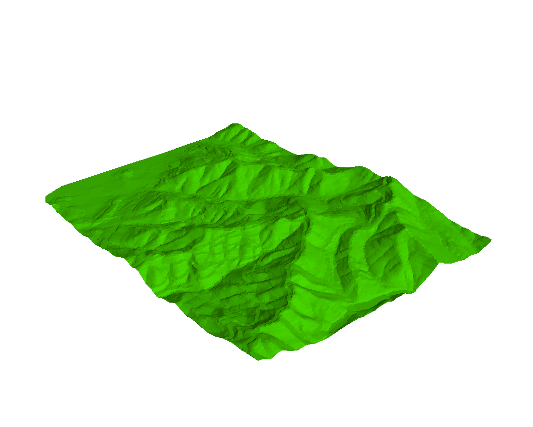
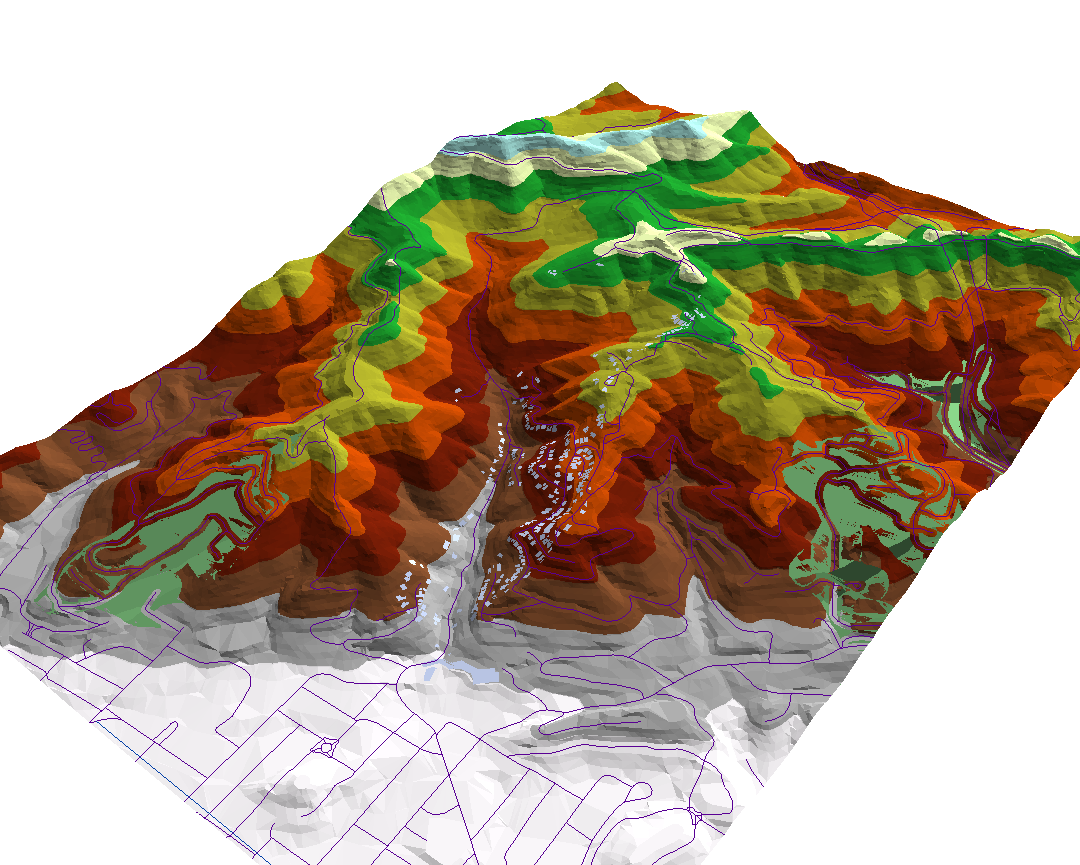
Personally, I feel that the increased contrast makes the 3D rendering look a bit better. It is interesting that changing the azimuth and altitude can dramatically change the way the landscape looks. My final view looked like this:
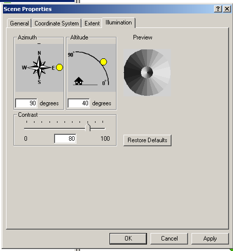
I gave the faces a green color, rotated the map, and changed my illumination properties to be as follows:
Personally, I feel that the increased contrast makes the 3D rendering look a bit better. It is interesting that changing the azimuth and altitude can dramatically change the way the landscape looks. My final view looked like this:
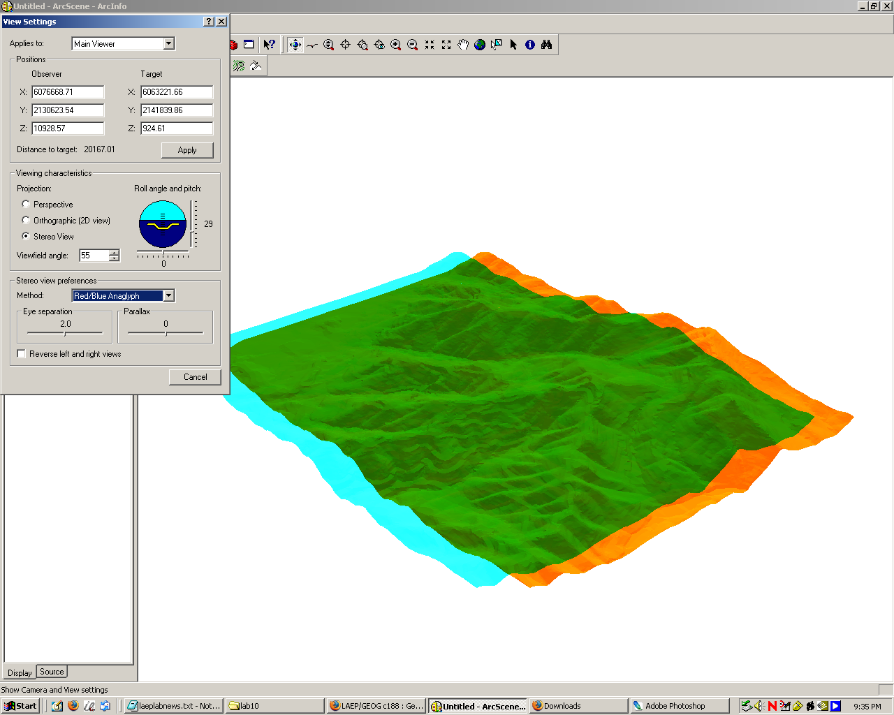
While poking around with the view options, I also noticed that ArcScene has the capability of rendering the view in stereo. That's pretty cool, assuming I had the hardware to actually take advantage of the feature.
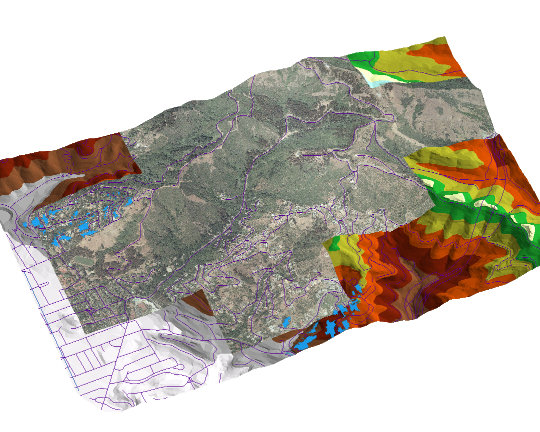
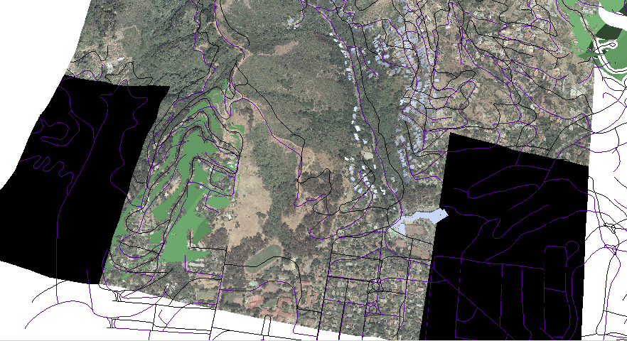
For picking my perfect sites, I decided to go back to the data I generated in lab 8. However, I ran into an interesting problem: for some reason, that data was misaligned in comparison to the rest of the dataset provided for lab 10. Curious to find out why, I went ahead and added that data (green polygons), the roads layer from lab 8 (black lines), the roads layer from lab 10 (purple lines), and the Claremont Canyon aerial image into ArcScene to see what was up. It turned out that the data was in fact shifted a bit:
I went into ArcMap, added the roads from lab 10 and the suitability data from lab 8 and went into edit mode. I then selected all of the polygons of the suitability shapefile, chose "Modify features" as my operation, and dragged and dropped the selection until it lined up properly with this lab's roads. This was fairly easy to do since my suitability data carved out a 40-ft buffer around all roads, so I just had to make sure that these empty spots were centered on the appropriate roads. With this fix in place, the data now looked OK:
We can also see here that there is some rendering strangeness when the TIN layer is turned on. I later found out how to fix this, as will descire later on this page.
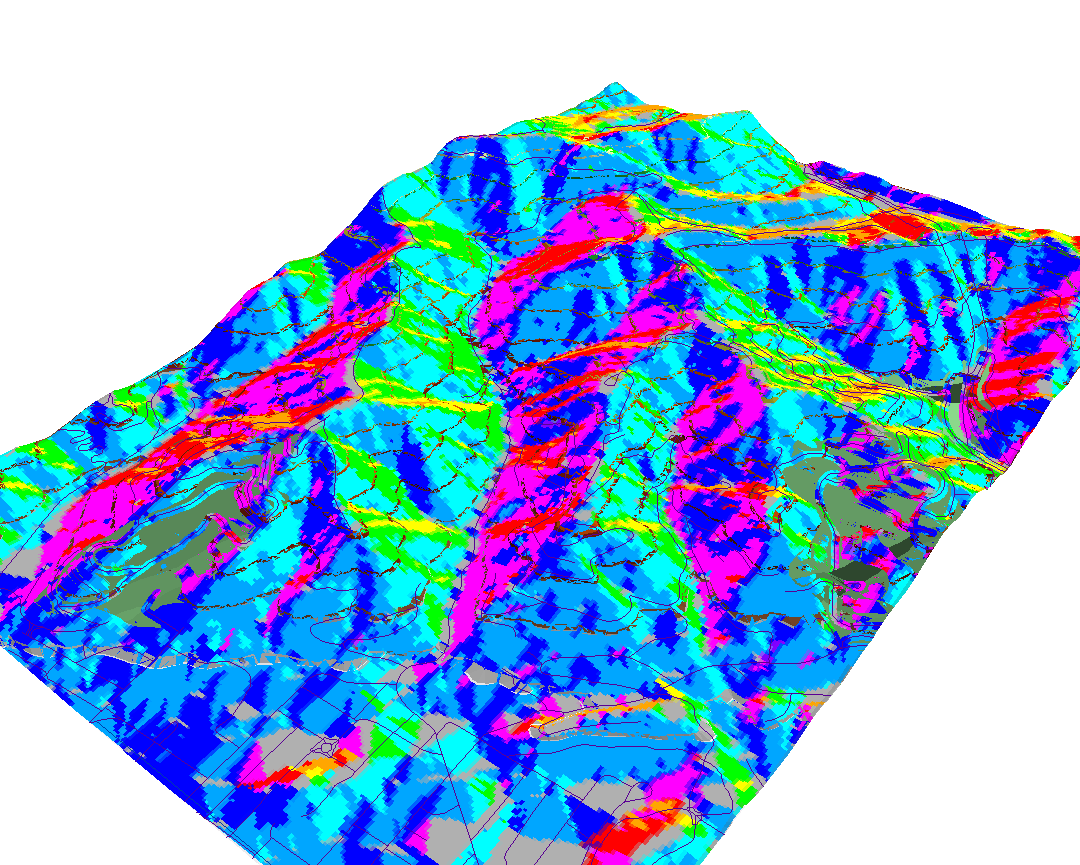
I now had a better idea of how to manipulate aspect and viewshed than in lab 9, so I went ahead and redid those analyses. I was surprised that ArcScene did not have a raster calculator, so I ended up doing all of my analysis in ArcMap and then simply using ArcScene to do the final rendering. First, I went ahead and generated the aspect for the entire TIN. In ArcScene, it looked like this:
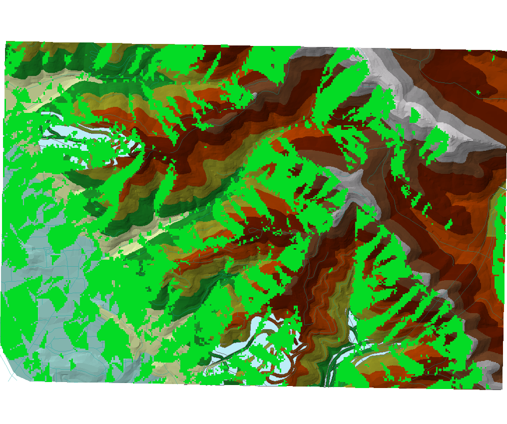
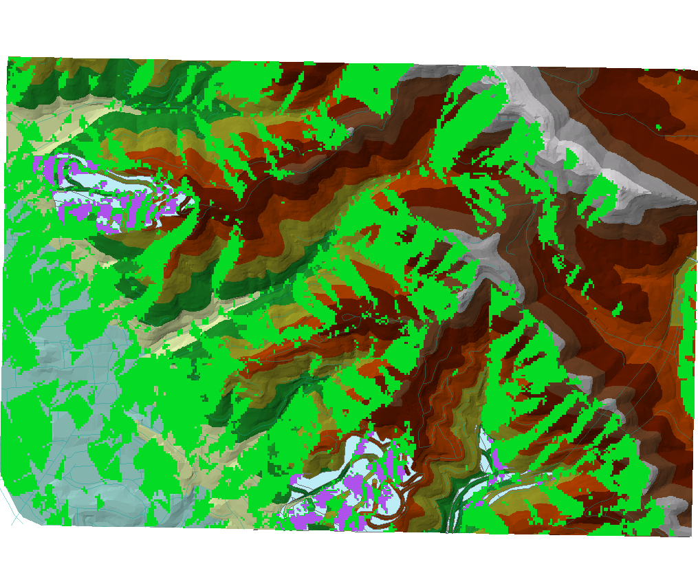
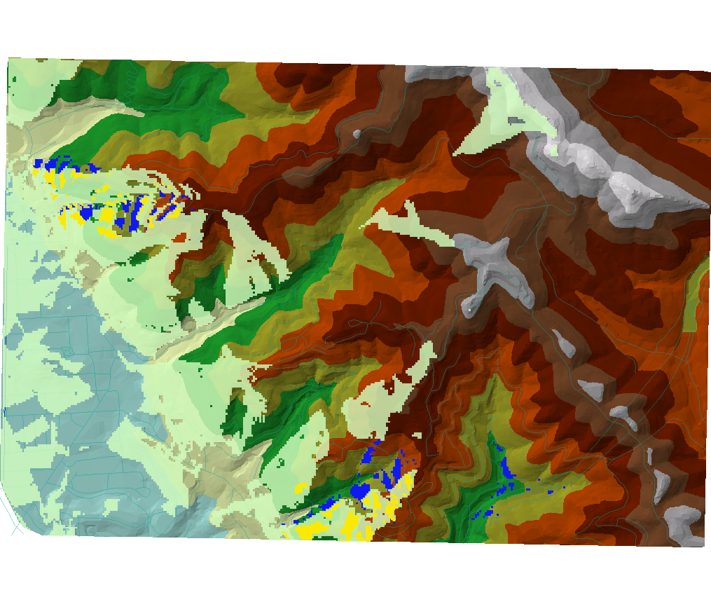
Then, I performed the calculation 315 > Aspect > 225 with the raster calculator. This map shows the result: calculation value 1 is in green, and the suitable regions are barely poking through in a light blue:
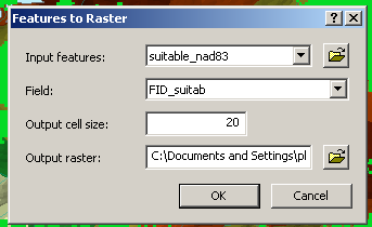
Then, I converted the suitable regions shapefile into a raster as follows:
For some reason, the polygons themselves had a value of "0" in the raster, so to get the intersection of my suitable area with the desired aspect, I had to perform the following calculation in the calculator:
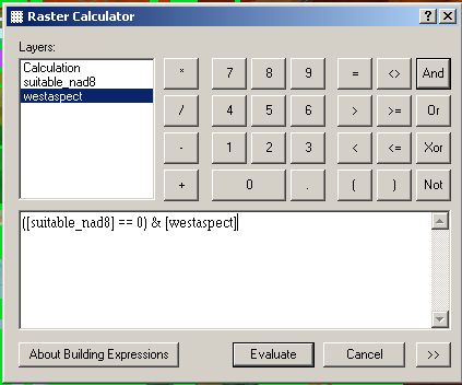
...which gave me the following map: aspect calculation value 1 is in green, suitable sites are in light blue, and their intersection is in purple.
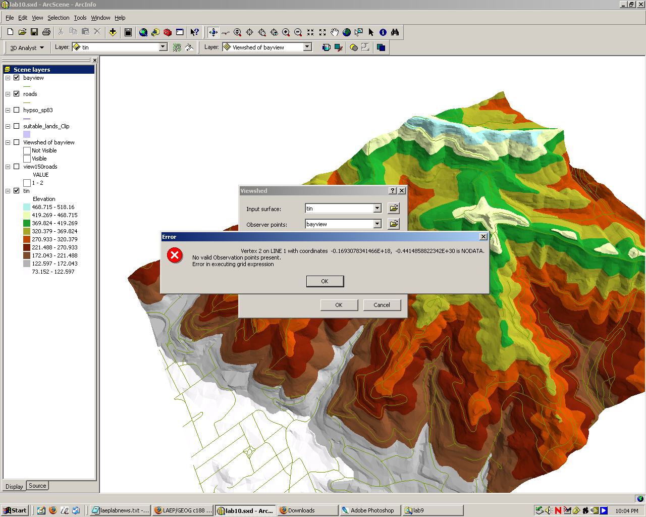
I then tried to go ahead and properly create a viewshed on the TIN with a line across the western edge of the map as the lookout point. For some reason, however, ArcScene was not happy with the observer point from my lab 9:
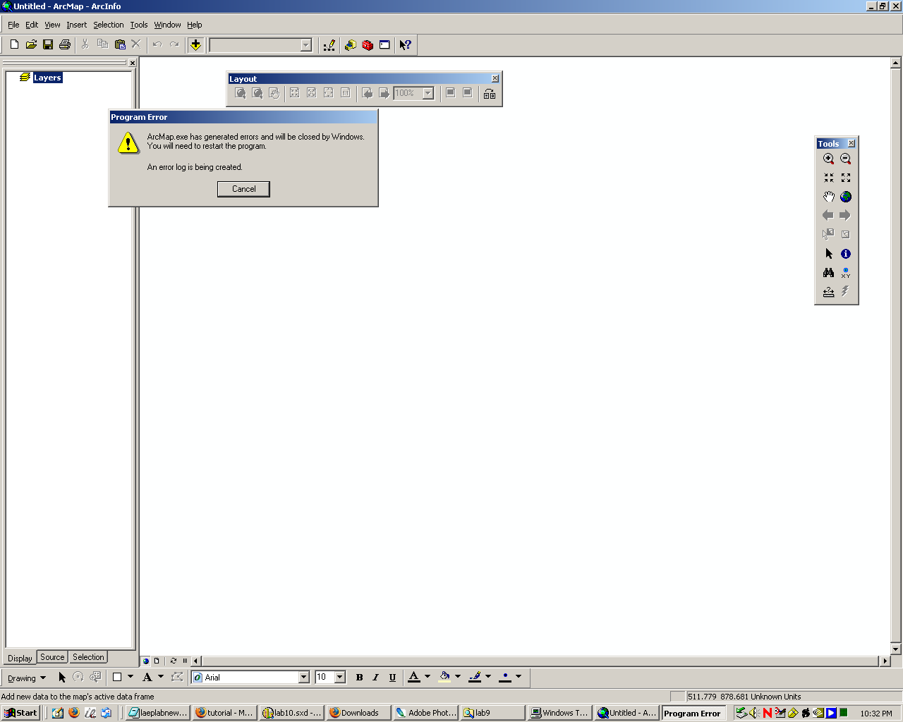
So, I went ahead and just created a new shapefile with the TIN's projection. ArcMap, however, would crash every time I tried to add the new shapefile to my layout. It would do it consistently. I had to come in a day later to try again, when ArcMap was feeling a bit better.
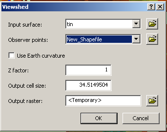
The following day all was well and I was finally able to make my line across the map. Then I was able to properly run the viewshed analysis with it as the observer and the TIN as the input:
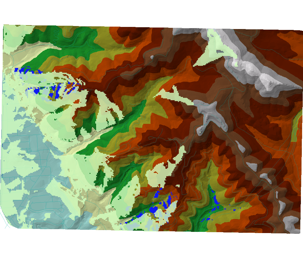
which resulted in the following map: viewshed is in a semi-transparent green, the result of the previous calculation in dark blue, and the colored elevation TIN as the backdrop. The idea is that "visible" sites in the viewshed will have a decent view of the San Francisco Bay.
As I discovered in the previous lab, the viewshed raster actually contains both values 1 and 2 for "visible" regions, so I made a somewhat more complicated raster calculation to intersect the viewshed with my suitable, western-facing sites:
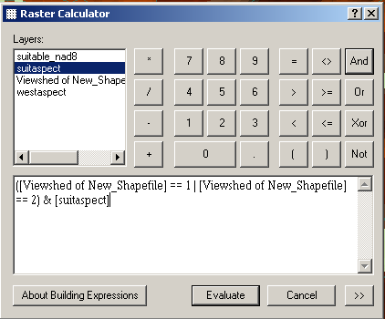
The result of the intersection can be seen on this map in bright yellow:
I saved this result as a GRID file and then imported it into ArcScene to get the following scene:
This was the end of my work in ArcMap and now came time to put it all together in ArcScene.
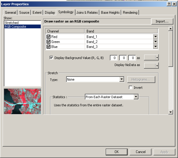
I added the Claremont Canyon aerial photo, the roads shapefile, my suitable sites raster calculation result, and the TIN to my scene view. However, there were a number of strange things. First, the sites would not show up above the aerial photos. I went ahead and removed the black background from the photos (for locations with no data) by going into the raster symbology and checking the box that said "Display background value as" and then selecting "No color" for the color:
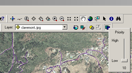
After doing this, the TIN would show up from behind the aerial photo but would also "bleed through" the photo at elevation color boundaries, making the view look really ugly. What was particularly strange about this was that the TIN was placed above the aerial photo in the table of contents. It turned out that the trick to getting this to work properly was the "priority" option in the Effects toolbar, seen here:
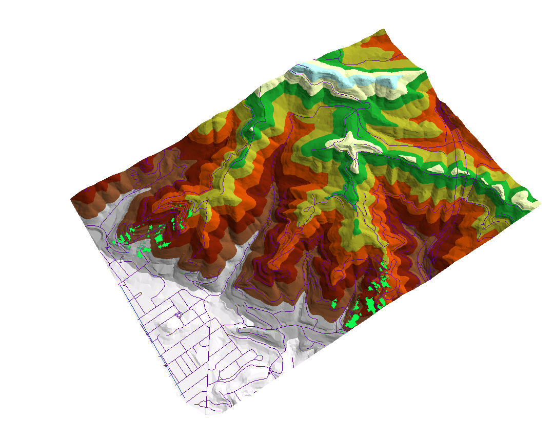
So I simply set the priority for my suitable sites to 1, the TIN to 10, and the aerial photo to 9. I gave the suitable sites a different color to make them stand out more, with this as my final product: